|
 |
|
 |
|
|
|
|
|
|
|
|
|
|
|
|
|
|
|
|
|
|
|
|
|
|
|
|
|
 |
Last page update was 09 May 2016 |
 |
|
|
May 2016
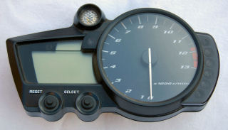
Yamaha R1 Instruments
My original plan was to not use the R1 instument cluster or 'clocks' but, these are the only way to get error codes out of the ECU. I purchased some second on eBay and set about wiring them up. This was not helped by the fact that I removed this wiring from the loom, to reduce weight.
|
I bought these R1 clocks a while back, with the intention of using them for diagnostics. They are the only way to read the error codes from the ECU. I don't intend to mount these permanently in my car. They are too heavy for that! :-) They are purely for diagnostics.
|
|
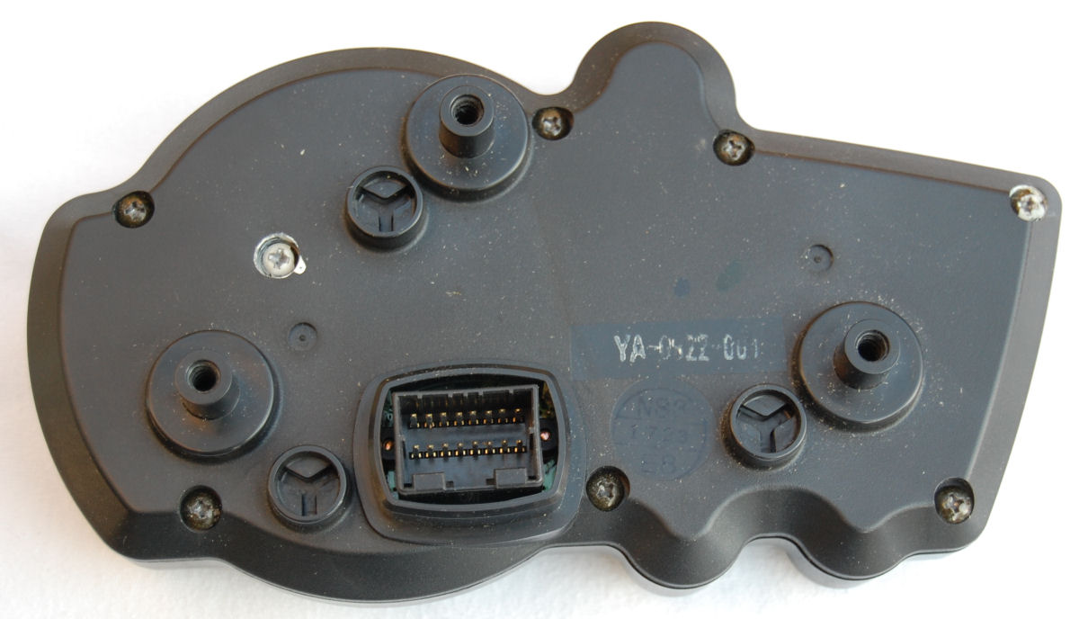
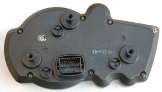
They have a 16-way connector socket on the back and I bought a plug to match it from Yorkshire Engines.
|
|
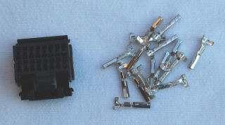
They have a 16-way connector and pins.
|
|
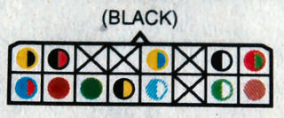
The R1 wiring diagram shows the original wiring to the plug on the header harness (I never bought this bit of the loom as I never planned to use it). These are as you look into the face of the plug. You need to flip these horizontally if you want to map them to the connector on the back of the instrument pod.
|
Four of the pins on this connector are not used at all and I only need to connect up four myself:
- Black/White = Earth from ECU (
- Brown = +12V from ignition switch
- Yellow/Blue = Serial data line from ECU (pin 38)
- Yellow/Black = Tachometer feed from ECU (pin 4)
|
|
|
|
|
|
|
|
|
|
|
|
|
|
|
|
|
|
|
|
|
|
|
|
|
|
|
|
|
|
Copyright © Robert Collingridge 2004 |
|
|
|