 |
|
|
|||||||||||||||||||||||||||||||||||||||||||||||||||||||
|
|
|
|||||||||||||||||||||||||||||||||||||||||||||||||||||||
| Essential Reading: |
The plumbing on the R1 engine is fairly complex with many outlets/inlets and it is important to get it right as the R1 engine has a water cooled oil cooler matrix and you really need to be sure that this is working correctly. Some people have tried to simplify or alter the R1 cooling system design, usually resulting in problems. Richard ![]() plumbed it up as designed and his car has been running for over three years without any problems on road or track. There are some additional pipes on the 2003 fuel-injected engine, making it slightly more complex. These are to implement a water temperature driven automatic choke. For the long gaps between the radiator and the engine, I'm using aluminum pipes, since this is lighter and cheaper and they will also not sag.
plumbed it up as designed and his car has been running for over three years without any problems on road or track. There are some additional pipes on the 2003 fuel-injected engine, making it slightly more complex. These are to implement a water temperature driven automatic choke. For the long gaps between the radiator and the engine, I'm using aluminum pipes, since this is lighter and cheaper and they will also not sag.
There are several issues to consider with this installation in a car though:
|
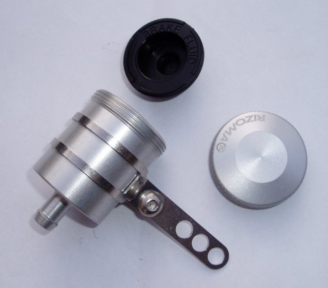
I bought a Rizoma fluid tank |
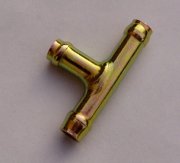
| To fit the tank another Yamaha 7mm T-piece is required (as used to connect the water pump breather pipe to the head and choke) to connect it to the thermostat breather pipe. The exact location of this needs to be thought through so that it will not hit the bonnet. |
|
Richard |
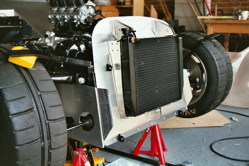
You can see the temperature sender on the radiator in the above picture. The 2003 radiator does not have this as the sensor is in the thermostat housing.
It is worth spending some time with a wooden tooth pick, straightening the fins on the R1 radiator. The easiest way to do this is to take off the fan and to hold it up to the sunlight. If you can see dark patches, then the fins are bent. They are very thin and weak, hence easy to straighten (and break!).
The radiator has three mounting points with rubber lined top-hat bushes (6mm bolt hole and 13mm deep). A couple were missing on my radiator but the bushes were bought separately from Orwell Motorcycles ![]() (part no. 90387-07391) for a couple of quid. The radiator needs to be mounted at the right height to clear the bonnet. Not sure if this is common, but my radiator is slightly warped. My design to mount it can accommodate this though.
(part no. 90387-07391) for a couple of quid. The radiator needs to be mounted at the right height to clear the bonnet. Not sure if this is common, but my radiator is slightly warped. My design to mount it can accommodate this though.
For the purposes of pipework the following imperial to metric conversions are used: 1/4" = 6.5mm, 3/8" = 9.5mm, 3/4" = 19mm, 1" = 25mm. I find the interchangeable use of units confusing, so I've stuck with metric units. As you can see from the diagrams below, the general flow is up through the engine block and into the thermostat assembly. It then feeds into the upper right side of the radiator, as does the hot flow from the oil cooler. Cooled water exits the left side of the radiator and is fed back into the bottom of the engine. The complex arrangement of pipes and radiator, ensures the correct and balanced flow rates.
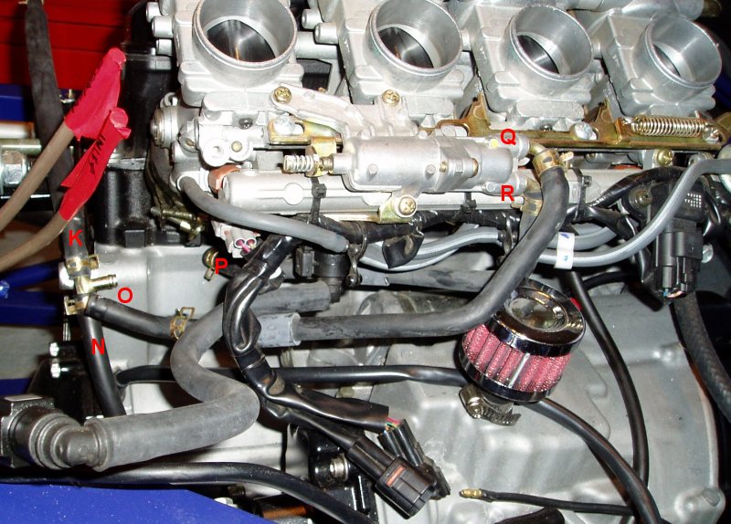
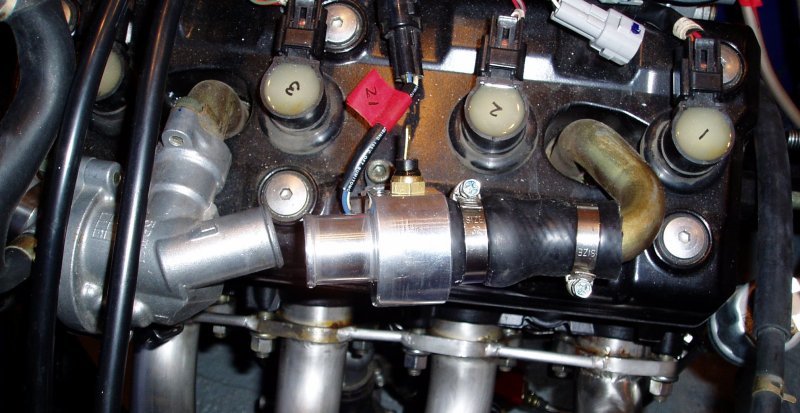
| This part of the cooling system is not described in the R1 service manual, so I'll try to describe it here. The automatic choke takes a feed [R] from the cylinder head [P] and then passes this back [Q] into the cooling system via a T-piece [O] into the oil cooler breather pipe circuit. The easiest way to connect this lot up was to use the existing rubber pipes. Note that this image shows [P] not actually connected in the right place yet but the head outlet is hidden from view. |
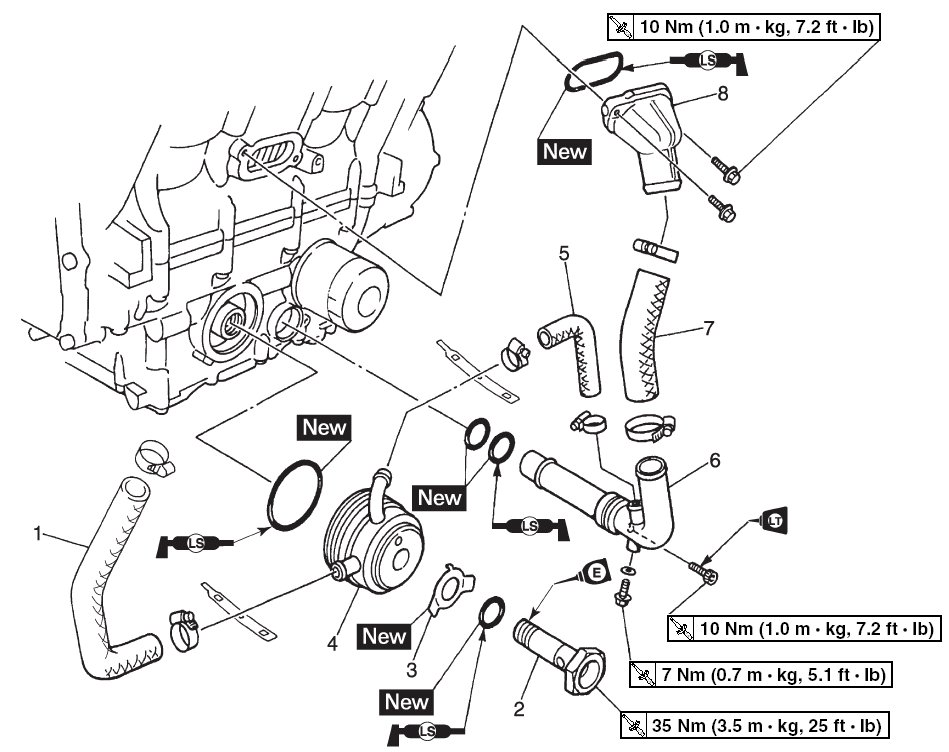
| One part of the cooling system I will leave alone is the water pump outlet pipe (6) and the connection pipe (5) to the oil cooler (4) and connection pipe (7) to the water jacket (8). In this diagram, all I will change is the oil cooler outlet hose (1), which now goes off to the radiator. |

|
I need to insert the 1/8" NPTF Digidash temperature sensor into the cooling circuit. I bought this 25mm diameter adaptor with the right sensor thread (part number GLOHA25) for Ł15.75 + VAT from Demon Tweeks |
|
On all of the R1 engine installations I've seen, this is mounted in the radiator inlet pipe. Daz |
|
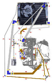
I've put together a MS Powerpoint slide for the cooling design. Existing Yamaha rubber pipes are shown in brown and new aluminium tubing shown in grey. Existing hose clips are shown in orange and new hose clips required in yellow. Pieces of silicon hose required are shown in blue.
My plumbing design is based upon black silicon hoses from Silicon Hoses |
| ID | Location | Description | 13mm hose clips |
20mm hose clips |
32mm hose clips |
| [A] | Radiator (Water Pump Breather) | 6mm pipe --- 6.5mm straight (50mm long) --- [T4]. | 2 | ||
| [B] | Radiator Outlet | 25mm pipe --- 25mm 90° elbow --- [T2]. | 2 | ||
| [C] | Radiator (Thermostat Breather Inlet) | 6mm pipe --- 6.5mm 45° elbow --- [T5]. | 2 | ||
| [D] | Radiator (Main Inlet) | 25mm pipe --- 25mm 45° elbow --- [T1]. | 2 | ||
| [E] | Radiator (Oil Cooler Inlet) | 14mm outlet --- 13mm 90° elbow --- [T3]. | (2) | ||
| [F] | Thermostat T-Piece (Radiator) | [T5] --- 6.5mm 45° elbow --- 6mm T-piece. | 2 | ||
| [G] | Thermostat T-piece (Thermostat) | 6mm T-piece --- 6.5mm straight (50mm long) --- 6mm Thermostat (Breather Outlet). | 2 | ||
| [H] | Thermostat T-piece (Air Tank) | 6mm pipe --- 6.5mm straight (50mm long) --- [T4]. | 2 | ||
| [I] | Air Catch Tank Inlet | 7mm inlet --- 6.5mm 90° elbow --- [T4]. | 2 | ||
| [J] | Thermostat Outlet | 25mm outlet --- 25mm 45° elbow --- [T1]. | 2 | ||
| [K] | T-piece (Radiator) | 6mm outlet --- [H4]. | 1 | ||
| [L] | Water Pump Inlet | 25mm inlet --- [H1]. | 0 | ||
| [M] | Water Pump Breather | 6.5mm outlet --- [H2]. | 1 | ||
| [N] | T-piece (Water Pump Breather) | 6.5mm outlet --- [H2]. | 1 | ||
| [O] | T-piece (Choke) | 6.5mm outlet --- [H3]. | 1 | ||
| [P] | Head (Choke) Outlet | 6.5mm outlet --- [H6] | 1 | ||
| [Q] | Choke (T-piece) (top) | 6.5mm outlet --- [H3] | 1 | ||
| [R] | Choke (Head) (bottom) | 6.5mm outlet --- [H2] | 1 | ||
| [S] | Oil Cooler (Radiator) | 13mm outlet --- 13mm straight (50mm long) --- [T6]. | 2 | ||
| [T] | Thermostat (Breather Outlet) | 6mm pipe --- 6.5mm straight (50mm long) --- Thermostat T-piece. | 2 | ||
| [U] | Water Temp Sensor (front) | 25mm outlet --- sensor housing using part of [H7] | 2 | ||
| [V] | Water Temp Sensor (rear) | 25mm outlet --- sensor housing using part of [H7] | (2) | ||
| [W] | Breather pipe | [T4] --- [H4] | 1 | ||
| [X] | Radiator inlet | [H1] --- 25mm hose joiner --- 25mm 90° elbow | 1 | [Y] | Radiator inlet | 25mm 90° elbow --- [T2] | 1 | [Z] | Radiator inlet | [T6] --- [H5] --- [T3] | 2 |
This requires the following lengths of aluminium tubing. All aluminium tubing will be beaded.
| [T1] | 25mm aluminium straight tube (700mm long) |
| [T2] | 25mm aluminium straight tube (800mm long) |
| [T3] | 13mm aluminium tube (280mm long). |
| [T4] | 6.5mm aluminium tube (930mm long). |
| [T5] | 6.5mm aluminium tube (750mm long). |
| [T6] | 13mm aluminium tube (400mm long). |
Richard ![]() and Chris
and Chris ![]() both filled their cars with Red Line Water Wetter
both filled their cars with Red Line Water Wetter ![]() to improve cooling. It seems to work well so I have bought a 355ml bottle (which will treat 15 litres of coolant and equates to a ~2.5% mix ratio) for about Ł20. Water Wetter doesn't do anything to raise the freezing point so anti-freeze is still required. The R1 engine has a convenient drain plug at the lowest point.
to improve cooling. It seems to work well so I have bought a 355ml bottle (which will treat 15 litres of coolant and equates to a ~2.5% mix ratio) for about Ł20. Water Wetter doesn't do anything to raise the freezing point so anti-freeze is still required. The R1 engine has a convenient drain plug at the lowest point.
The R1 cooling system is 2.45L in capacity. With the additional pipework, I estimate it to be about 3L in total, so for a 50:50 mix I've used 1.5L of antifreeze.
I'm using the Yamaha Yamalube coolant as it is silicate and boric free.
|
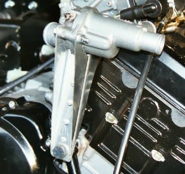
The thermostat housing is normally mounted to the engine block. This picture shows how Richard |
It is actually simpler on the 2003 engine to leave the thermostat housing in place. By doing this I can re-use all of the existing pipe work (head to choke, choke to inlet, etc.), except the bits that connect to the radiator.
|
|
|
|||||||||||||||||||||||||||||||||||||||||||||||||||||||