 |
|
|
|||||||||||||||||||||||||||||||||||||||||||||||||||||||
|
|
|
|||||||||||||||||||||||||||||||||||||||||||||||||||||||
And all before Christmas!
| I fitted this to the car to get it out of the way. |
|
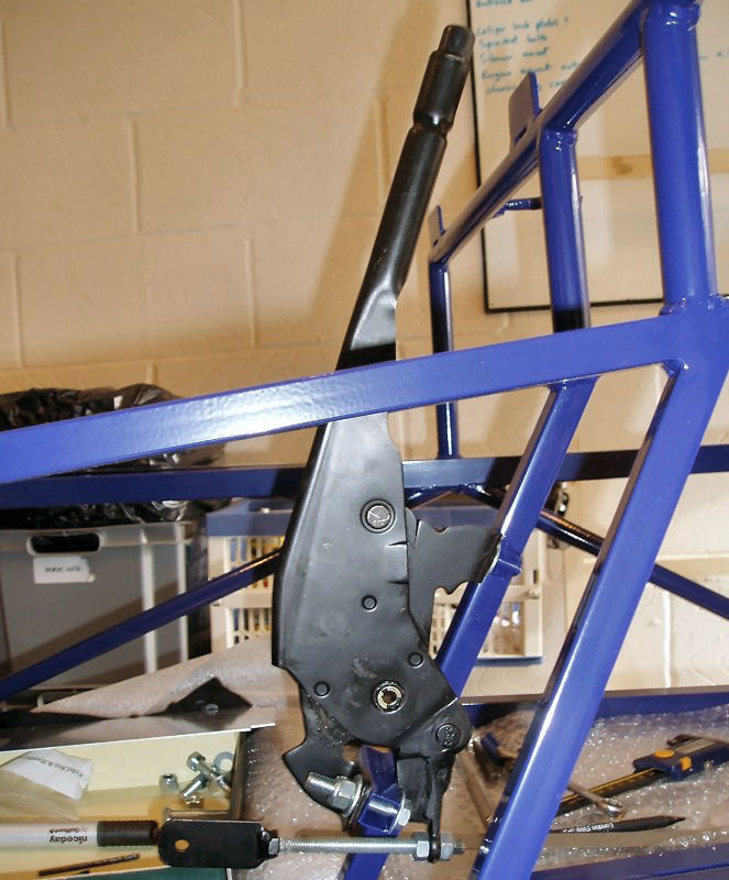
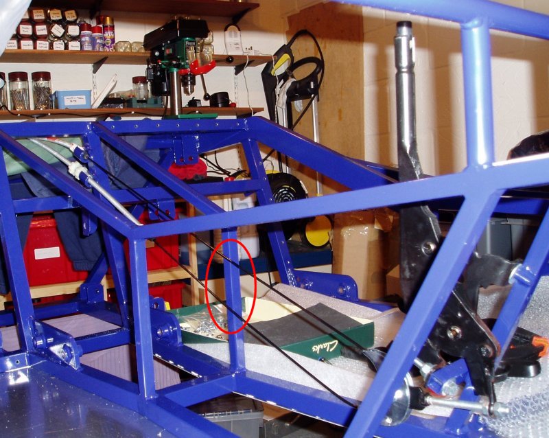
While I was playing with the handbrake I thought I'd fit the cable too. This has to go in the right way, with the adjuster in the bottom cable slot. It's a 6mm x 25mm bolt to fix the cable to the handbrake.
Whilst I was fitting this I noticed that the cable will rub on the chassis where the tunnel narrows (circled in linked picture). I'm not sure if this will be a problem at SVA time. |
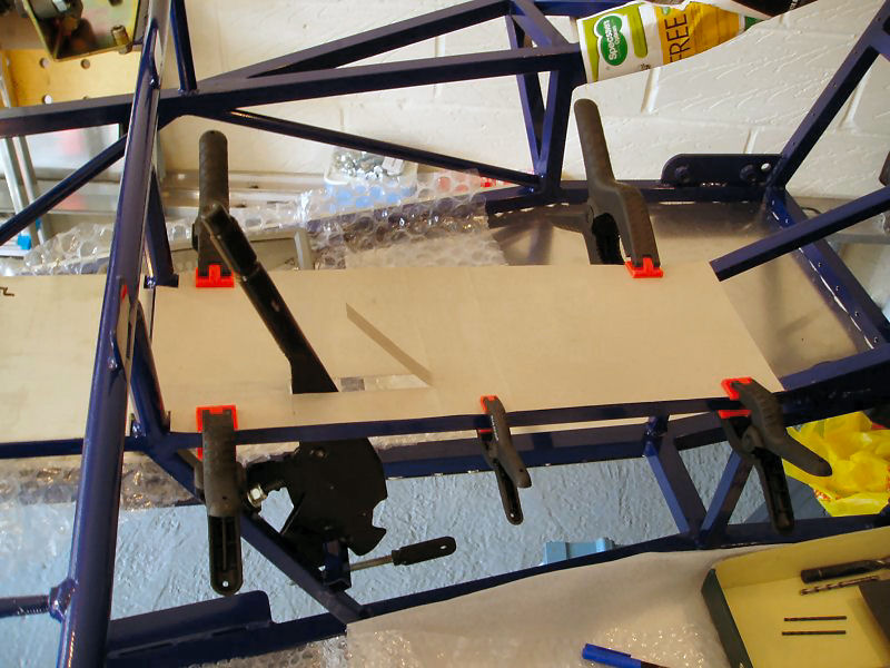
| Fitting the handbrake distracted me on how best to fit the panel over/around it so I cut a cardboard template from the supplied panel. I measured where the handbrake would need to sit and its likely travel. I cut a slot in my template and checked it aligned. This surfaced one issue. The button end is wider than the rest of the handbrake, so I'm going to need a 20mm diameter hole at one end of my slot to thread the panel over the handbrake. |

| Having checked the cardboard template worked I mapped the template markings across to the supplied panel, drilled out the 20mm hole and the cut the slot. I plan to replace this aluminium panel with a carbon fibre one at a later date, so I'm using rivnuts to hold it in place. This will also make access easier later. I also had to bend the rear edge of this panel slightly to fit the chassis rails. |
Fixing rivnuts are something else I've never done before. For this panel I'm using six of them (5mm thread, 6.8mm diameter) and I drilled the usual 3mm pilot holes through the panel and chassis rails. I drilled the panel out to 5mm and cleaned and polished it up for powder coating. I opened the holes in the chassis rail to 7mm and fixed the rivnuts.
|
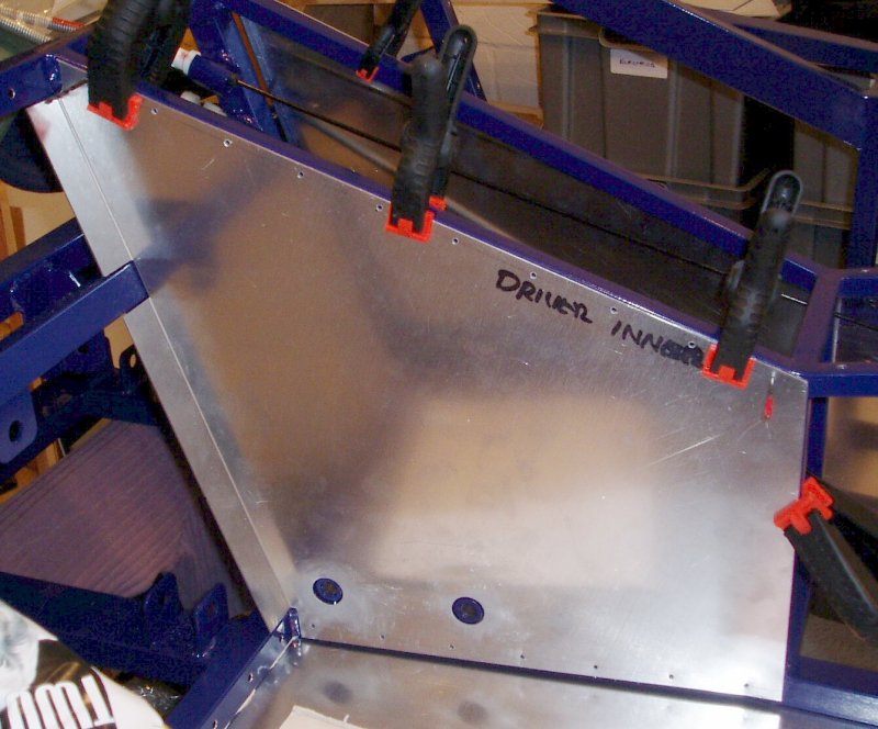
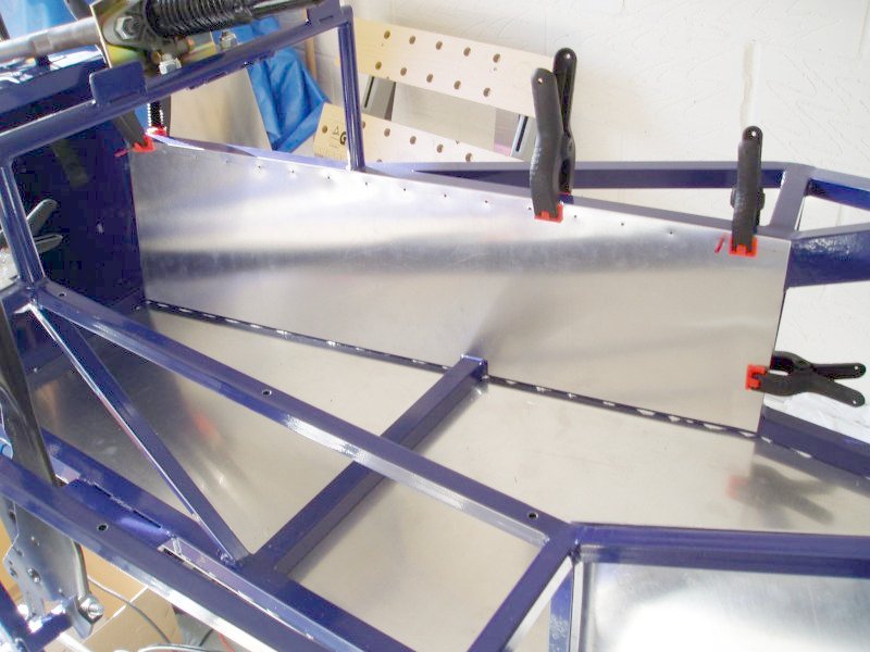
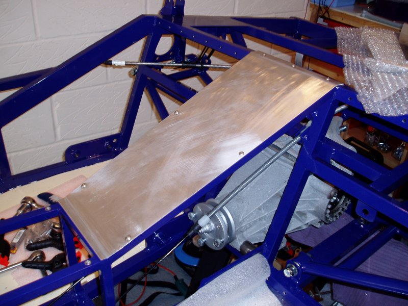
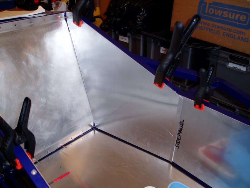
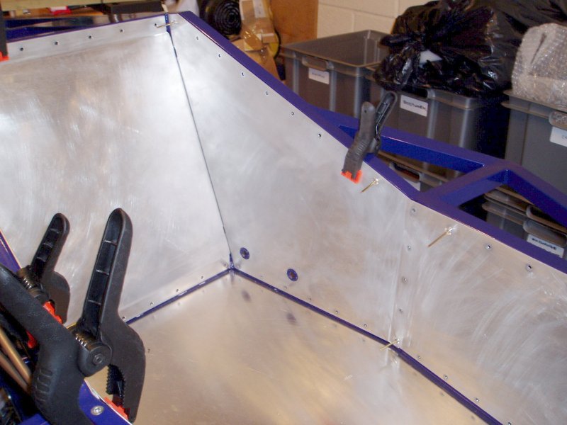
This panel has to be fitted before the bulkhead panel as the folded part goes behind the bulkhead panel and the two are riveted together. The holes also need to be cut for the seat belt mounting points. This panel needs some modification to clear the chassis rail across the rear bulkhead.
Having got the position right, I held it in place with two 3mm drill bits in pilot holes and some clamps. It took a long time to get it to sit right and to cut and file around the chassis rail and welded joints. The next challenge was to cut the holes for the harness mounts to show through. I wiggled a pencil round and round, through the mounts and this left a circle on the back of the panel indicating where to make my 22mm holes. I then removed the panel and tidied it all up, ready for powder coating. |
On the face of it, I haven't achieved much in my mornings work but I'm taking my time to do it right. I only want to do this bit once! I can't see how people can avoid powder coating the panels though. I've been as careful as I can but they have loads of marks on them, which I'm going to have to polish out.
For use with black panels you can also get black rivets but I want to use the normal ones.
3rd November
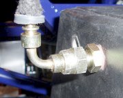
My plan was to run some brake pipes but I got as far as fitting the rear T-piece on the chassis rail above the differential, using a 6mm rivnut and bolt. I need a special tool to cut the pipes which I won't have until next week. I then got curious about what would be unreachable once the rear bulkhead panels had been fitted and ended up putting the lower rear wishbones on the car. The bolts have to go through the mounts the right way or you will never be able to get them off again (without removing the bulkhead panels). Having tie-wrapped these up out of the way, I got thinking about the outlets on the fuel tank, so I trial fitted this in place with some roof straps. I noticed that all the inlets and outlets are already clear and do not need to be drilled through.
|
I'm also missing an adaptor fitting for the tank fuel return line. I ordered another one from The Kit Car Workshop |
| The tank is a really odd shape with a trapezoidal side profile. Don't know why this is the case. It's going to make fabricating the tank fixing straps interesting. |
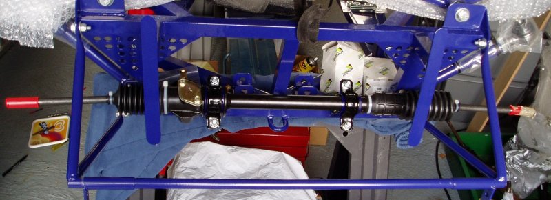
One thing led to the next and I started to think about how the differential would fit in through all the chassis rails. And that led me to ...
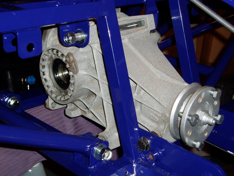
| This next bit took me the best part of the evening. The new 2006 chassis has different fitting to those I've seen on earlier Fury's. It has the long 10mm x 240mm bolt going across the top but, there are two spacers for the lower front holes and a 10mm bolts goes through an extra hole in the 6-point harness mount. Finally there is a rear tube welded on the chassis for the rear 8mm bolt. |
Fitting the long bolt was relatively easy but the two lower ones were a nightmare, compounded by the fact that the set of bolts supplied to fit the differential are obviously for the 2005 chassis and these two bolts were missing. I had some suitable ones to hand but fitting them took ages. I used thread locking compound as I don't want this flapping about with 160+bhp going through it.
5th November
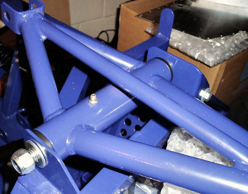
Fitted the front suspension lower wishbones to get them off the floor and out of the way. These can't be fully tightened up until the car is on the floor since the rubber bushes need to flex away from their 'at rest' point (and not sit under tension) and this can't be done until the car is on the floor. I also can't get right ball joint to go in to the wishbone more than 10mm. I'll try swapping them over as the left one goes in all the way (about 50mm). The amount by which these are threaded in or out is used to set the camber (which also can't be done yet).
6th November
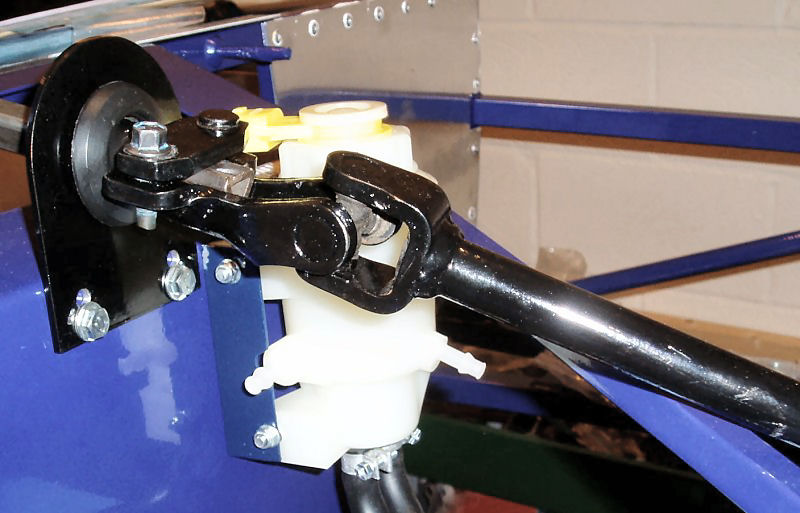
| Made a 90° bracket to mount the brake fluid reservoir to the footwell as the additional spare (sealed) outlets get in the way. I made this up from some aluminium angle and painted it to match the powder coat. Riveted it to the end of the drivers footwell. |
Painted steering column extension with black Hammerite smooth. Swapped the front ball joints over and with a bit more force, managed to get them both to wind in properly. It seems the threads on one ball joint are larger/tighter than the other.

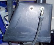
| Fitted the brake fluid reservoir using 5mm bolts and nylocs and plumbed it up to the brake cylinders. Made the mistake of undoing one of the hose clamps to ease it up the rubber hose. Once they are undone, they are a nightmare to get back together. |
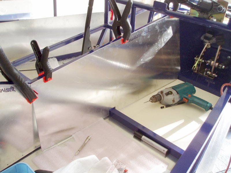
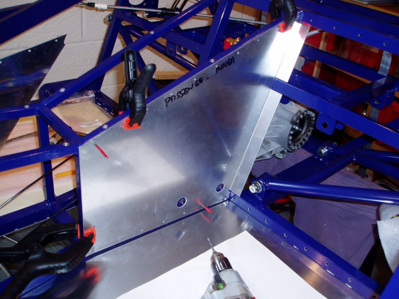
| Having decided to fit the outer panels on the inside of the chassis, I started by having a look at the drivers front side. This panel needs to be modified as a chassis rail goes across the car midway along it. This one also needs a bit more work though as it is too long and the front edge also needs modifying to get the right angle on it. The rear edge will overlap with the rear outer panel (this one on the outside) and where they overlap the rivet holes will have to be drilled through both panels at the same time. |
|
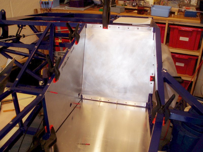
Putting this on the inside of the chassis is going to make fitting it a easier. The downside is that the additional length now has to be folded out of the way though, to fix to the rear chassis rail. The only way to see how this might work was to cut a cardboard template out using the supplied panel. I then cut this to fit around the various chassis rails and to see where the fold needs to be made. This panel will also need holes cut for the harness mounts.
I've never folded sheet aluminium before and all I had to do it with was some lengths of hardwood, some clamps and a large hammer. As it happened, it worked out really well and I'm very happy with the finish. With the fold made, I drilled some pilot holes to hold the panel in place whilst I then marked up the remaining modifications required. It's only when you have all the panels in place that you can check they all go together as planned. |
| The last panel to do on this side of the car! I'll be glad when the paneling is over. I'm not sure if I'm working very slowly or just being very thorough but, the paneling seems to be dragging on a bit! This panel is flat but has to mount onto a set of non-parallel chassis rails. This means that although the panel has a straight edge and mounts onto straight rails, it needs modifications to get a nice even finish. I clamped it and drilled two pilot holes. In centre punching the rivet holes, the panel actually gets bent to fit the compound shape required. This one also overlaps a rear panel, on the outside. |
On the face of it, not much has been achieved for a whole mornings effort but I've now finished all the drivers side panels. I've deburred them, polished them, cleaned them up and they are all wrapped up in bubble wrap to go to the powder coaters. There is about as much work as I expected to panel a Fury but, it is just taking so much longer than I expected. My target of getting the engine going before Christmas is looking optimistic.
A colleague at work has just got his R1 Striker back from the exhaust manifold fabricators. He used the same company that I plan to use. He is very happy with the work they have done for him, which bodes well. I've got some aluminium on order to fabricate my silencer mount and fuel tank brackets.
For the 22mm holes around the harness mounts, I've used a round hole saw. I'm sure this was designed to cut wood but it makes a good job of cutting holes in thin aluminium sheet, though it does get very hot!
I've got two full-face head guards in my garage (from Screwfix) so that there is always one to hand. These are cheap (£8 each) and comfortable and they keep your face looking the way it was meant to be.
9th November
Bugger! Found a 'small leak' in our ensuite bathroom, which seems to have been there for a while. Slight pause in progress whilst my attentions turn to completely gutting, re-flooring, plastering, tiling and fitting a new bathroom suite :-(
10th November
Spent the whole day working on the bathroom. My bits are ready to be collected from the powder coaters and my pieces of aluminium have arrived.
11th November
Picked up my powder coated parts. They look fantastic, especially the paddle shift. The front uprights look like new and finally getting the steering rack mounts mean I can now progress the front suspension installation.
| Fitted the steering rack using 8mm bolts. |
|
I'm still waiting on some washers from The Kit Car Workshop |
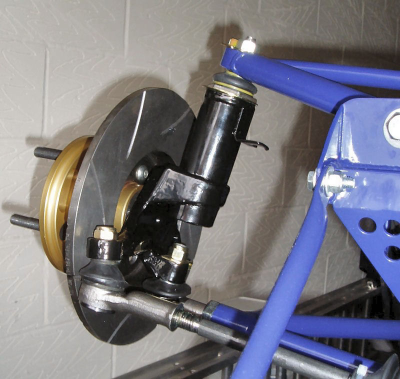
| I fitted this to make sure the steering rack was centred, so that the steering wheel will turn the same amount in both directions. With it centred I can then check that the uprights are facing in the right direction. I tried to fit it and realised I had made a mistake somewhere. It seemed to be too long and it rested on a chassis rail. I had to move the steering column end plate (bolted to the end of the footwell) up about 10mm to get it to fit correctly. |
How do you stop the ball joint rotating whilst you tighten it? The approach I used was to wedge it in hard so that it gripped when tightened. What torque should it be done up to? Not sure yet.
The downside of putting the front uprights on, is that my car is now a lot wider and I had to reorganise stuff in the garage to get around the car more easily. Without the springs/dampers in place the suspension arms will droop under the weight of the uprights. These extreme angles can damage the ball joint rubbers. To hold the suspension arms in place horizontally, I loosely fitted the spring/damper bolts in place and used some cargo straps between them.
|
My front hubs came with the inner bearings pre-fitted by The Kit Car Workshop |
| It's about time I got on and finished the paneling. They are due to be powder coated next week. I started with an easy one to ease myself back into it :-) |
Started looking at fuel tank straps and rear uprights.
17th November
Picked up a brake pipe flaring tool from my work motor club.
| With my various fixings delivered by Namrick I can now put together a few more things like my paddle shift lever. |
I also started work on my fuel tank mounting straps as the foam arrived from NF Auto.
18th November
Bought a vice as I one to hold the brake pipe flaring tool in and it should make bending the fuel tank straps easier.
22nd November
The rear bolt on the differential in particular is a right pain to get in. The chassis mount and the differential simply do not align with the other bolts in place. I'm going to have to use some brute force to get this bolt in but so far all attempts have failed. Until this bolt is in, I can't put the petrol tank on.
Having wasted a decent part of the morning on this, I need to get back to the paneling ...
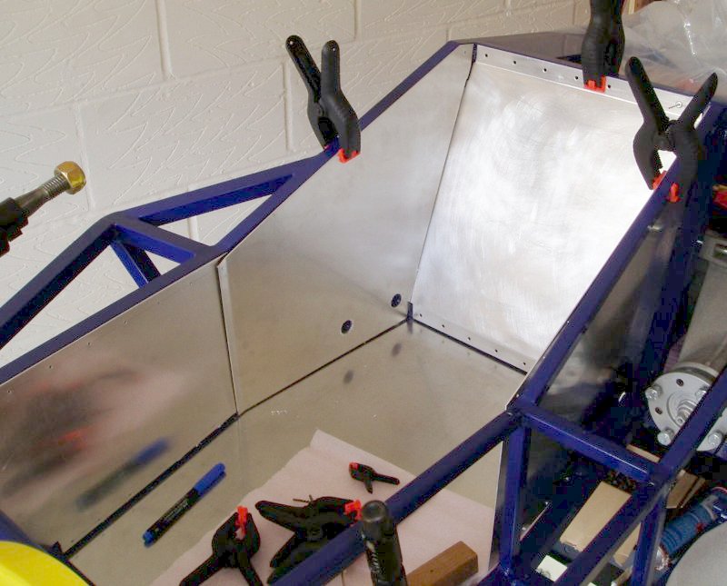
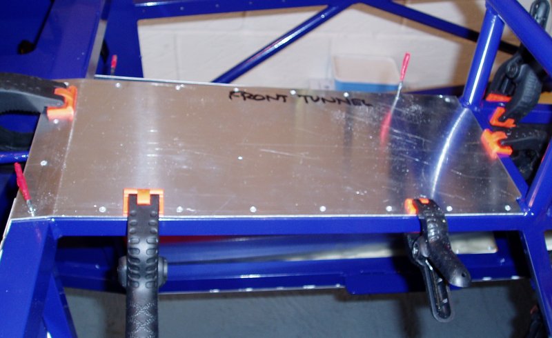
| The front end of this panel overlaps the centre tunnel top panel. The time consuming part is tidying up and polishing the panels, ready for powder coating. |
| This panel has to be done before the rear bulkhead as it folds behind it. It needs holes cut for the harness mounts. |
| I have done this panel already but it needs trimming down to fit now that the above panel is in place. |
|
The additional length has to be folded out of the way, to fix to the rear chassis rail, through the bulkhead panel. As with the other side, I didn't know this when I drilled the holes for the rear bulkhead panel so I'm going to have to align the panels and work out where the blind holes are again. I cut a template again using some card sheets. I cut the template to fit around the various chassis rails and welds and to see where the fold needs to be made. I also cut holes to expose the harness mounts. My unusual approach to panel folding seems to have worked even better this time and I'm very pleased with the fit and finish. Didn't manage to quite finish it in this session but, I see an end to the paneling in sight now! |
Out of curiosity, I wondered just how accurately can you set this anyway. The granularity of adjustment is one 360° turn of the ball joint, which equates to a movement of 1.5mm (the thread pitch). The distance between the upper and lower ball joint pivot points is about 215mm, so one turn equates to an adjustment of 0.40°.
24th November
I kept the old bolts from my Escort uprights and the bolts used to hold the calipers on are not metric. I'm going to need some shorter ones (25mm or 1") for my Hi-spec calipers though as the existing ones go too far through the uprights and would hit the brake disks.
Cut the lengths of fuel pipe to see how it should run along the tunnel. The return pipe looks easy enough but the feed pipe is going to have a more convoluted route due to the handbrake cable and mounts.
Started to look at the radiator mounting and fabricating some mounting brackets from aluminium.
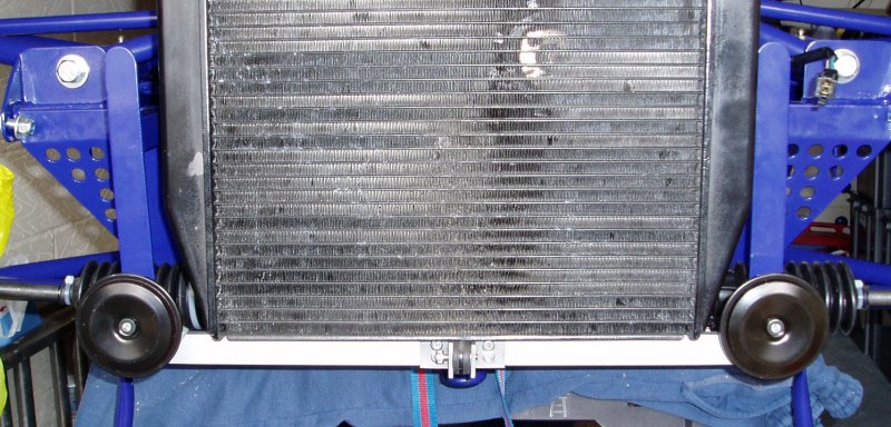
| Made up a lower mounting bracket, which also doubles up as a mount for the twin horns. Very 'Colin Chapman'. |
| Finished this off and tidied it up for powder coating. |
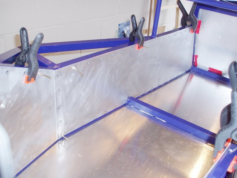
| This panel needs to be modified as a chassis rail goes across the car midway along it. The rear edge will overlap with the rear outer panel (this one on the outside) and where they overlap the rivet holes will have to be drilled through both panels at the same time. I had to file the top down quite a lot to get it to nicely follow the contour of the upper chassis rail. |

| This panel is flat but has to mount onto a set of non-parallel chassis rails. This means that although the panel has a straight edge and mounts onto straight rails, it needs many modifications to get a nice finish. I clamped it and drilled two pilot holes. In centre punching the rivet holes, the panel actually gets bent to better fit the compound shape required. This one also overlaps the rear outer panel (on the outside). |
Lessons learnt from paneling the car (assumes panels on the inside):
30th November
Dropped all my panels off at the powder coaters to be done in gloss black. Also picked up some bolts for the front calipers.
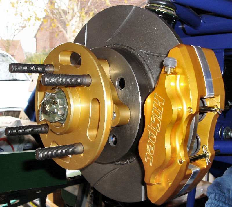
| These bolt to the front uprights and need to be centred on the brake disks (use washers to achieve the correct spacing). Mine fitted perfectly when bolted straight to the uprights. These M12 x 25mm bolts are torqued up to 110Nm. My old caliper locking plates are a bit of a mess and I don't know where to source new ones from. I'll worry about this later. |
|
|
|
|||||||||||||||||||||||||||||||||||||||||||||||||||||||