 |
|
|
|||||||||||||||||||||||||||||||||||||||||||||||||||||||
|
|
|
|||||||||||||||||||||||||||||||||||||||||||||||||||||||
My original plan was to go for classic white dials but by the time I'd priced these up with all of the required senders, it was going to be simpler and more cost effective to fit a Digidash ![]() from ETB Instruments
from ETB Instruments ![]() , like Richard
, like Richard ![]() did. This provides a neat and SVA compliant solution with data logging. The Digidash is made by Custom Autotech
did. This provides a neat and SVA compliant solution with data logging. The Digidash is made by Custom Autotech ![]() and there is loads of useful calibration and installation data on their web site. It is not cheap but it does all I need and the data logging is a very useful diagnostics tool. It also comes with all the required sensors. Another advantage is that it is very compact and light-weight.
and there is loads of useful calibration and installation data on their web site. It is not cheap but it does all I need and the data logging is a very useful diagnostics tool. It also comes with all the required sensors. Another advantage is that it is very compact and light-weight.

| The Digidash has built in shift lights and is SVA compliant with the exception of the outer edges of the casing. If the DigiDash is mounted outside the diameter of the steering wheel (+127mm) then the radius of the case edges would not pass the internal projection test. |
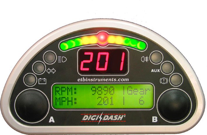
| A new version, Digidash2 is now available. The spec is the same but this version has G sensors built in and a CAN bus connecting the display unit to the logger unit, which is now separate. It costs a little bit more but has a clearer and better display and looks superb. |
Two magnets mounted at 180° on the propshaft interact with the sensor to the Digidash. Richard ![]() glued his on a cleaned propshaft with Araldite. The resulting pulses go to the digidash unit which can be programmed with a conversion factor, to convert this into the correct speed readout. The speedo is obviously only correct if there is no wheel spin though. The magnets are also mounted on the propshaft between the gearbox and the torque resilient tube section of the propshaft, to minimise the effects of the TRT and the differential slack.
glued his on a cleaned propshaft with Araldite. The resulting pulses go to the digidash unit which can be programmed with a conversion factor, to convert this into the correct speed readout. The speedo is obviously only correct if there is no wheel spin though. The magnets are also mounted on the propshaft between the gearbox and the torque resilient tube section of the propshaft, to minimise the effects of the TRT and the differential slack.
RPM is measured either off a coil or the tacho feed from the Cdi unit. There is an input for the neutral switch too. If no switch is present or the rpm is out of range for any gear it knows of, it simply displays "C" for coast.
For SVA the digital speedo must show the maximum possible speed reading (to ensure it does this for the speed range of the car). For the Digidash, ETB have a standard FAX to send if required by the test centre. This states what the maximum display speed is. The next build of the digidash software (V3.20) will state this on power up to overcome this problem. For the DD2, this is not a problem as it is designed to state this on power up.
The Digidash comes with its own oil pressure sensor. This basically connects via the earth and if you short it directly to earth, a reading of 140psi should be obtained.
I'm assuming that I will need a different configuration for track days. The shift lights will be much closer together and I won't want a speed warning coming on at 100mph!
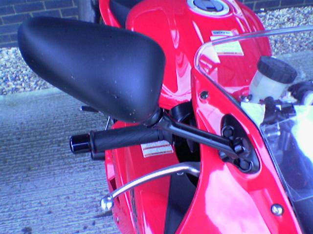
| The mirrors are from a Suzuki SV650S and are highly rated by those that have put them on a Fury. They offer a very good field of view and are resistant to the vibrations found on motorbikes and in BECs. The genuine Suzuki parts cost £72.76 for the pair, from my local bike dealership. Expensive but, they are an essential safety feature in my view and worth the money. They are supplied black but, I'm going to see how easy/expensive it is to get them painted to match my bodywork. |
With hindsight: There are plenty of Suzuki mirrors on eBay in varying condition. I picked a decent pair up for £20. They work really well.
|
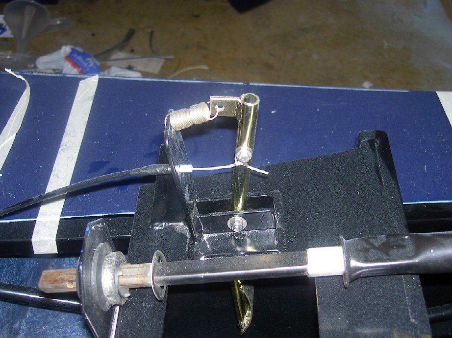
Chris Although the cable and return spring effectively define the pedal 'start' point, any slack in the cable would mean it could move when the throttle is closed and then the initial slack take-up would reflect in a poor pedal feel and response. To overcome this, I've used the existing cable mount on the pedal arm to acts as a hard 'start' point, by mounting an end stop (bolt)on the cable upright. This means that I can pre-tension the cable slightly to remove any slack and improve the feel. |
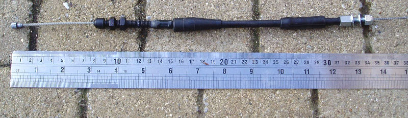
| The throttle pedal in the Fury is designed with a single cable (with spring return) in mind, so I simply removed the throttle return cable from the throttle bodies. The other cable is too short but has just the right metal fixings to the accelerator pedal. I used the straight from the removed cable on the pedal end. I had a bicycle brake bolt with cable hole in it left over from a previous project. |
Since the existing cable is too short I needed to find a longer cable to replace it. The cable sheath needs to be about 90cm long. Normal bicycle cables do not have barrel nipples with the same dimensions. The closest thing I could find was a Shimano brake cable with nylon over caps. When the nylon caps were removed, there was a barrel nipple inside with 6mm diameter and 9mm in width. This is close enough though and fits the throttle bodies without fouling anything. This cable was also 2mm in thickness but this caused no problems, apart from the fact that I needed to find an outer sheath to match it. I could still use the R1 cable fixings with this cable.
The only problem I found with this approach is that the existing spring cannot be fitted as it is now going to either be loose or too tight to fit. I'm not really sure what the spring does. All it seems to do is add about 25mm of 'slack' to the clutch arm. I think this is because it allows the bike lever to be easy to pull in with the tips of your fingers on the bike and then harder when you can use all of your fingers to actually operate the clutch. I fixed this by removing this spring completely.
| My clutch cable was made by shortening the one that came with the bike engine and by using a bit from the left over return throttle cable. The pedal end should mount to the footwell bulkhead. There is an 18mm diameter hole drilled for the cable but this assumes the cable is in line with the pedal and is using the supplied mounting point on the pedal. As I'm moving the cable mounting point upwards (to get less movement), I may need to drill a new hole. The end bit nicked from the old throttle cable requires a 6mm hole to bolt through. I also intend to clamp the cable to the pedal using a bolt with a hole through it. This means that my new hole also needs to move to the left a bit to align with the edge of the pedal. |
Getting access to drill a new hole is going to be very difficult so I may cheat and fabricate an offset adaptor that fills the 18mm hole and provides a new 6mm one. This is definately worth a try first.
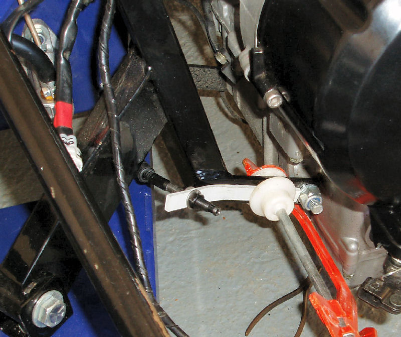
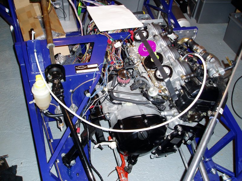
| The engine end of the clutch cable needs to be mounted somewhere solid and also provides the right pull angle for the cable. The only way I could see of doing this was to bolt a bracket to the engine mount. This will require two 5mm holes in a very solid part of the mount (5mm thick x 25mm wide steel), so I'm not concerned about weakening the mount. This picture shows my first attempt (temporarily clamped to the mount) in 3mm aluminium but this may flex too much and I will probably make something for permanent use in 5mm steel. The clutch cable end requires an 8mm hole in the mount. Cable tension adjustment is via the clamp bolt on the pedal. |
The mounting point on the pedal needs to be chosen carefully to provide the same amount of movement of the cable on the bike (about 15mm) and to also provide decent pedal travel for the right feel. It's a compromise though because as you gear the movement up to provide more pedal travel, you decrease the feel and the feedback effect of the clutch spring. Richard ![]() used a cable mount point that was 35mm away from the pivot point.
used a cable mount point that was 35mm away from the pivot point.
Paddle Shift Gear Changer
The paddle shift gear changer is covered in the transmission section.
|
|
|
|||||||||||||||||||||||||||||||||||||||||||||||||||||||