|
 |
|
 |
|
|
|
|
|
|
|
|
|
|
|
|
|
|
|
|
|
|
|
|
|
|
|
|
|
 |
Last page update was 03 Jun 2020 |
 |
|
|
Fisher Fury R1 Engine Electrics
The R1 wiring loom is in two main parts. The main engine loom is the only one I need. If you want to use the bikes instruments, then you will also need the header loom. I also got some of the smaller lighting looms included with my harness. I didn't get anthing to do with the handlebar switches and this is not required.
With hindsight:
I should have left the wiring parts intact for the R1 clocks. I'm now adding this wiring back in to allow me to use some R1 instruments for diagnostics.
This is the bike loom as it was delivered. Some sensors are attached, that were connected to the bodywork. It took me about 90 minutes to go through and label up all the connectors and identify stuff I could remove from this loom. About half of the wiring is redundant in a car installation as I will have seperate wiring for the lights, horn, fuel pump, etc.
The first thing you need is this wiring diagram from the service manual. For ease of use/download, I've separated it out into its own, one-page PDF document (153Kbytes). This is clear and usable when printed on an A3 colour laser printer.
This Haynes version of the wiring loom is a large JPG file. It's better in some respects as it puts stuff into better perspective but, it is not totally accurate in my view.
There are seven sub-harness connectors labelled A to G on the circuit diagram:
- Sub-harness A = Cord Head Light, white connector, 10 way. Not connected in my design.
- Sub-harness B = Cord Head Light, 6 way. Not connected in my design.
- Sub-harness C = Cord Tail Light. Not connected in my design.
- Sub-harness D = Wire Sub Lead 1, grey connector, 6 way. Connects the coils/plugs to the main loom.
- Sub-harness E = Wire Sub Lead 2, grey connector, 3 way. Connects the air sensors to the main loom.
- Sub-harness F = Wire Sub Lead 3, black connector, 6 way. Connects the fuel injectors to the main loom.
- Sub-harness G = Wire Sub Lead 4, black connector, 4 way. Connects the oil pressure and crank position sensors to the main loom.
I've stuck with numbering and naming convention from the service manual:
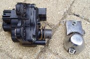
01 - Main Switch
A 2-pole switch with two seperate connectors to it. One pole switches power to all circuits, the other operates some of the starter circuit logic. You can permanently connect together the blue-black and blue-yellow wires. This means a standard single pole key-switch will work for as a main switch.
02 - AC Magneto (Alternator)
Mounted on the engine, grey connector, 3 pins.
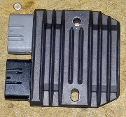
03 - Rectifier
|
Black connector, 3 pins, 2 wires, thick red + thick black. On a bike, the rectifier is well placed to keep it cool. In a car it needs to be placed with thought. Mounting on an aluminium plate/heatsink with thermal transfer compound is a must. Many people also add a fan to keep it cool. It weighs 315g.
|
04 - Backup Fuse
In main fuse box. If the main fuse fails, this ensures power still goes to the bike multi-function meter (38).
05 - Battery
Thick battery cable to large black connection block (with 2 blade fuses), red + black. Lugs to connect to battery terminals on loom. I'm pretty sure these need to be lengthened. Best to replace the cables rather than extend them as they have standard connectors on both ends.
06 - Fuse Main
50A fuse in seperate, in-line, rectangular fuse box. Required.
07 - Fuse (Fuel Injection System)
White connector, 4 pins, white + red + red/white + blue/white.
08 - Starter Relay
Required.
09 - Starter Motor
Mounted on engine. Required.
10 - Starter Circuit Cut-Off Relay
Big black box, multi-way connector. Houses logic to enable/disable engine start. If all the right conditions are not met, the engine cannot be started. Required.
11 - Side Stand Switch
Blue connector, 2 wires, black + black/blue. The other end of this connector was attached to the engine and is attached to the oil level gauge (39) wiring by plastic clips. On my engine, just bare wires were left. Will short wires in loom to emulate stand permanently up.
12 - Fuel Pump
The fuel pump has two connectors to it:
- White connector (light blue inside), 2 pins, 2 wires, black + green/white. This connector seems to be for the fuel level warning light. I don't need this part of the loom as I have a seperate fuel level sensor driving the Digidash.
- Green connector (light blue inside), 2 pins, 2 wires, black + red/blue. I will use this to drive my fuel pump, either directly of via a seperate relay.
13 - ECU
You need it! It weighs 335g.
14 - Ignition Coil
These sit on top of the spark plugs. They just pull off to reveal the spark plugs.
15 - Spark Plugs
I use NGK Iridium CR9EIA-9 6289 spark plugs. The loom is numbered 1-4 so that you connect the coils to the right plug. According to the Yamaha R1 service manual the spark plugs should be checked every 6000 months or 4000 miles and replaced every 12 months or 8000 miles. The plug gap should be 0.8 to 0.9mm gap and the spark plugs are torqued to 13Nm.
November 2015 - Replaced the spark plugs at 12,700 miles
June 2020 - Replaced the spark plugs at 14,400 miles
16 - Fuel Injector
17 - AI System Solenoid
Not required as AIS system will be removed from engine.
18 - EXUP Servo Motor
Black connector (yellow inside), 6 pins, 5 wires.
|
This is required on a car and is a fairly bulky thing to hide in the engine bay. It is required to get the engine running properly and can be simulated electrically to save weight. JB Racing  sell a replacement module but it is �84 and that's a lot of money to replace 415g with something weighing slightly less. There is also a circuit shown here . sell a replacement module but it is �84 and that's a lot of money to replace 415g with something weighing slightly less. There is also a circuit shown here .
|
It is possible to run the engine with this disconnected but the ignitor unit senses the servomotor assembly missing, it generates a 'tach diagnostic' of the form that causes the tach needle to 'jump' between actual engine rpm, then to zero rpm, then 7000 rpm and repeat this sequence continuously. This tach diagnostic has been termed as the 'Tach Tango'. Samanna Systems have done a few tests and applied a 7.5K resistor in place of the EXUP motor unit and got better results but they also sell an emulator that results in no error codes when the R1 clocks are used.
The resistor solution is to connect a 7.5K ohm resistor between the black/red and the white/red wires from the R1 wire harness, which previously connected to the servomotor assembly. This will then eliminate the tach diagnostic except for when 1) The ignition key is in the 'ON' position and the engine is not running for a period of time greater than 12 seconds. 2) With engine idling, 'coasting' with the clutch lever pulled in. This is good enough for me as I'm not using the R1 clocks.
19 - Speed Sensor
The speed sensor is fixed to the engine block but this is the only sensor I've found where the wiring colours don't match the diagram. They should be black/blue + white + blue/yellow but they are actually pink + orange/red + black/white. The wiring loom has a white triangular connector, 3 pins, 3 wires, blue + blue/black + white/yellow. Required by ECU from what I can see but other owners say it is only required if you use the R1 clocks.
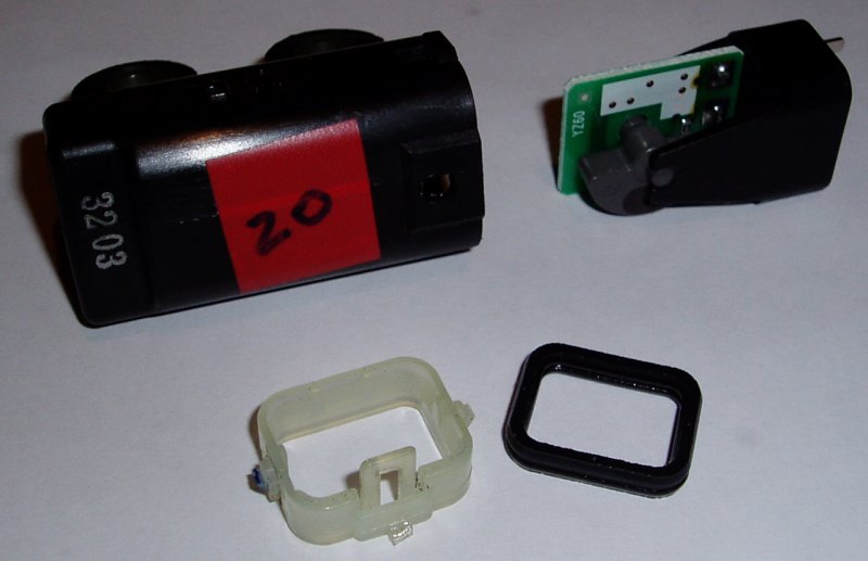
20 - Lean Angle Cut-Off Switch

|
This causes the ECU to cut the engine when the bike falls over. It is marked with 'UP' on one side, to ensure it is correctly orientated (but it doesn't stop you mounting it facing front/rear by mistake). It only weighs 30g but I wanted to remove it or disable it because it could be triggered by the g-forces of cornering (or braking/accelerating if you mount it wrongly) and could cut the engine mid-corner, with potentially disastrous results. It has three pins/wires to it (I'm assuming +12v, GND and a sense wire). Opening this sensor up reveals a small circuit board with a hall effect IC and a semi-circular pendulum with a magnet bonded within it. To disable its operation, I've simply glued the pendulum in place. I will now mount it as intended and leave it connected in the loom.
There are many people that replace it successfully with a 470ohm resistor between the yellow/green and black/blue wires.
|
21 - Cyclinder Indentification Sensor
I think this is used by the fuel injection system to work out which cyclinder to inject fuel in to.
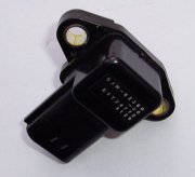
22 - Atmospheric Pressure Sensor
Grey connector (yellow inside), 3 pins, 3 wires, pink + black + blue.

|
The air pressure sensor is mounted on the throttle bodies.
|
23 - Intake Air Pressure Sensor
Required by ECU.
24 - Throttle Position Sensor
Fixed to engine. Required by ECU.
25 - Crankshaft Position Sensor
White connector, 2 pins, 2 wires, grey + blue/black. Required by ECU.
The crankshaft position sensor can fail and sometimes it does it intermittently. These two threads are worth a read if you have issues and are getting an error code 12:
- https://www.r1-forum.com/threads/how-to-replace-the-cylinder-identification-sensor-aka-cam-position-sensor.239070/
- https://www.r1-forum.com/threads/code-12-crankshaft-position-sensor.67362/
There are only two wires from the crankshaft position sensor to the ECU and one of these is a ground wire (black/blue), so the other wire (grey) is a signal wire and you would not expect to see 12V on this wire all the time.
On the motorbike a lot of the issues appear to be the with the ground wire as it is part of a bundle of ground wires in a block that can corrode. Obviosuly this could occur on a BEC too, depending on how the wiring look has been installed and modified.
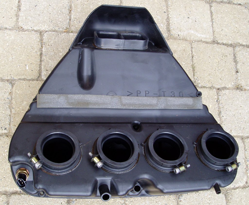
26 - Intake Air Temperature Sensor
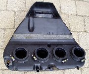
|
This is required and is found on the underside of the airbox (bottom left corner on photo). Requires a 17mm spanner to remove.
|
27 - Coolant Temperature Sensor
This is bolted into the thermostat housing. I'm not sure what the ECU does with the information from this but it must be required to optimise the engine running.
28 - Neutral Switch
This is required. Without it the ECU won't allow the engine to start. This is also connected to the Digidash unit for indicative purposes.
29 - Fuel Level Warning Light
Not present and not required. The sensor only drives a fuel level warning light on the multi-function meter unit (42).
30 - Oil Level Warning Light
Not required. The sensor (39) is connected to a light on the dash though.
31 - Neutral Indicator Light
Not required. The sensor is connected to the Digidash though.
32 - Tachometer
Not required.
33 - Coolant Temperature Indicator Light
Not required. Sensor connects to ECU though. A seperate temperature sensor is added for the Digidash function.
34 - High Beam Indicator Light
Not required. Car wiring loom connects to Digidash for this function.
35 - Turn Signal Indicator Light (Left)
Not required. Car wiring loom connects to Digidash for this function.
36 - Turn Signal Indicator Light (Right)
Not required. Car wiring loom connects to Digidash for this function.
37 - Meter Light
Not required.
38 - Meter Assembly
Not present and not required.
39 - Oil Level Gauge
Required and fixed to engine. Ordinarily this goes to the multi-function meter (42), with a warning light on it. I've connected this to a small circuit to drive a 12V LED warning light on the dash. From the wiring diagram it looks like this is a simple switch to earth but in reality it is an analogue sensor and measures 125ohms when empty and about 500ohms when full.

My solution to this is to use an LM311 comparator and a pair of voltage dividers to monitor the resistance and compare it to a reference voltage. The first voltage divider is adjustable but typically results in a voltage around 1.8V at point B. This is compared to the voltage at point A, which depends on the oil level sensor. When full this has a resistance of about 500ohms and thus point A is at 2.2V. As it empties it falls to around 125ohms and point A is then at 0.645V. This change is detected by the comparator and switches on the 12V red LED. The exact changeover point is adjustable via the 10K potentiometer. Through trial and measurement the potentiometer can be replaced with a fixed resistor. If the resistance of the sensor needs to be detected at around 400ohms then the variable resistor would need to be about 6800ohms.
There is no hysteresis designed in as I want a fast and responsive warning to a major failure. This is a backup system to the oil pressure sensor and the alarm facility on the Digidash. In order to stop it triggering on track days, the switch on point will be set relatively low.
40 - Turn Signal Relay
Small black box. Can be removed as it is not used in my design.
41 - Left Handle Bar Switch
Not present and not required. White connector, 10 pins, 9 wires. This would connect 43, 44, 45 and 46 to the main harness if I had it. 45 is the clutch switch and needs to be emulated for the engine to start.
42 - Multi-function Meter
Not present and not required. It's a shame the engine warning light is not exposed to the wiring loom from this as I would have liked to see this replicated on my dash.
43 - Dimmer Switch
Not present and not required. Part of the left handlebar switch assembly (41).
44 - Horn Switch
Not present and not required. Car wiring loom and dash switch supports this function. Part of the left handlebar switch assembly (41).
45 - Clutch Switch
Not present and not required. Connected to main loom via 41 and is not present. I will need to short the pins to enable the engine to start. Part of the left handlebar switch assembly (41).
46 - Turn Signal Switch
Not present and not required. Car wiring loom supports for this function. Part of the left handlebar switch assembly (41).
47 - Front Turn Signal Light (Left)
Not present and not required. Car wiring loom supports for this function.
48 - Front Turn Signal Light (Right)
Not present and not required. Car wiring loom supports for this function.
49 - Rear Turn Signal Light (Left)
Not present and not required. Car wiring loom supports for this function.
50 - Front Turn Signal Light (Right)
Not present and not required. Car wiring loom supports for this function.
51 - Horn
Not present and not required. Two shrouded 90° spades, 2 wires, black + pink. Could use this wiring but not thick enough to handle my intended horn, so I'll remove this wiring from my loom.
52 - Auxiliary Light
Not present, on sub-harness A.
53 - Head Light
Not present, on sub-harness A.
54 - Licence Plate Light
Not present, on sub-harness C.
55 - Tail/Brake Light
Not present and not required. White triangular connector, 3 pins, 3 wires, yellow + black + blue/red. Not used.
56 - Rear Brake Switch
Not present and not required. Brown connector, 2 pins, 2 wires, brown + yellow.
57 - Right Handle Bar Switch
Not present and not required. Blue connector, 6 pins, 6 wires. This would connect 58, 59 and 60 to the main harness if I had it. 59 is the engine kill switch and 60 is the start switch which need to be connected to my dash switches.
58 - Front Brake Switch
Not present and not required. Handle bar mounted switch, not present and not required.
59 - Engine Stop Switch
Handle bar mounted switch, not present and not required. These wires will be shorted to leave the engine in permanent 'run' state and the engine will be switched off via the main ignition switch (1). In the bike loom, normal operation is to switch power to the the starter circuit cut-off relay (10) and the spark plugs (15).
60 - Start Switch
Not present and not required. This is replaced by the dash mounted, engine start button. It connects the starter circuit cut-off relay (10) to ground and if all the other conditions are met, this then grounds the negative side of the starter relay (8), thus starting the engine.
61 - Head Light Relay (On/Off)
Not required. Car wiring loom supports this function.
62 - Head Light Relay (Dimmer)
Not required. Car wiring loom supports this function.
63 - Fuse (Ignition)
15A fuse in main fuse box. Required.
64 - Fuse (Signal)
10A fuse in main fuse box. Will be removed. This powers the indicators, the horn and brake lights.
65 - Fuse (Headlight)
20A fuse in main fuse box. Will be removed.
66 - Fuse (Fan Motor)
15A fuse in main fuse box. This will be used as the fan is controlled by the ECU. I'm taking a sense lead from this to an LED on the dash.
67 - Fan Motor Relay
White connector into black relay housing, 4 pins, brown/green + blue + red/white + green/yellow. This will be used as the fan is controlled by the ECU.
The fan relay coil is connected to a switched live feed via a red/white wire and activated by the other side of the coil being pulled to ground by the ECU via a green/yellow wire. This means the LED indicator on the dash needs to be lit in the same manner.
I've tapped in to the green/yellow wire to take a 12V feed to a blue LED on the dash, to provide an indication of when the fan is on. This needs to be done on the relay control sude as the fan also acts as a generator and will spin on its own at higher speeds and higher air flows. This will cause the LED indicator to glow even when the fan is off.
68 - Fan Motor
Black connector, 2 pins, 2 wires, medium black + medium blue. This feed/control comes from the ECU, via the fan relay is required and the output side is extended to reach the R1 fan at the front of the car. I extended the blue wire only, with the fan being earthed at the front of the car.
|
|
|
|
|
|
|
|
|
|
|
|
|
|
|
|
|
|
|
|
|
|
|
|
|
|
|
|
|
|
Copyright © Robert Collingridge 2004 |
|
|
|